There are many ways to make holes in the ground, and one of them is casing systems. In this article, we explain in more detail why they are used and how they work.
When drilling into ground, one of the simplest scenarios is having bedrock at the surface. If this is the case, a rock bit can be used to drill directly into the rock. However, this is a rare occurrence, and it is almost a given that drilling would start on a softer layer of ground – known as overburden – that could be several or even tens of metres above the rock layer. While rock bits can easily pass through overburden, the problem is that these holes tend to collapse.
Helical auger drills are an alternative method for effectively penetrating soft ground, but even a single larger rock can stop or at least significantly slow down drilling. Ground drilling almost never provides complete certainty of the subsurface conditions, so it is advisable to choose the most reliable and versatile method available.
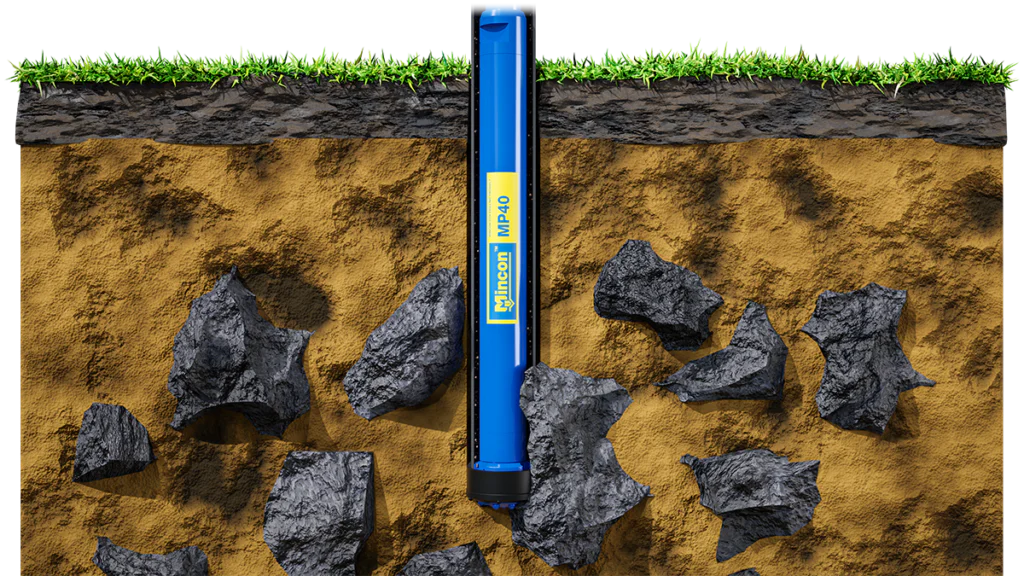
The Mechanics of Reliable Drilling
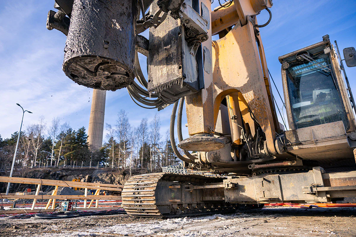
To address the challenge of reliably drilling through overburden and rock, casing systems have been developed – an approach where drilling is conducted using a casing pipe. This casing protects the hole from collapsing and it travels with the drilling all the way into solid bedrock. When used with DTH hammer drilling, this method can easily pass through rocks and boulders without impacting drilling progress.
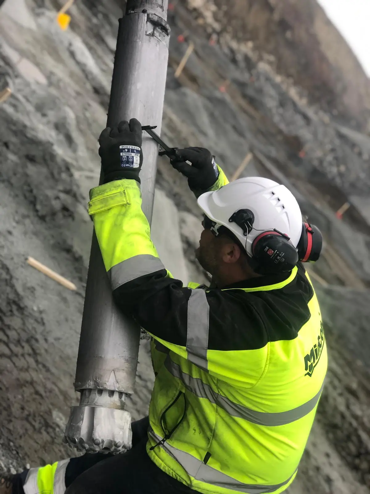
At the bottom of the steel casing, a casing shoe is welded to the casing, which in turn connects to the ring-bit – a ring-shaped cutting element slightly thicker than the casing wall. A pilot bit, connected to a DTH hammer, is then inserted through the casing, and the hammer is connected to the drill rig via drill pipes. In most cases, a shock absorber should be installed between the hammer and the drill string to protect the drill rig from recoil reflected from the rock. The assembly of casing shoe, ring bit and pilot bit, is called a casing system.
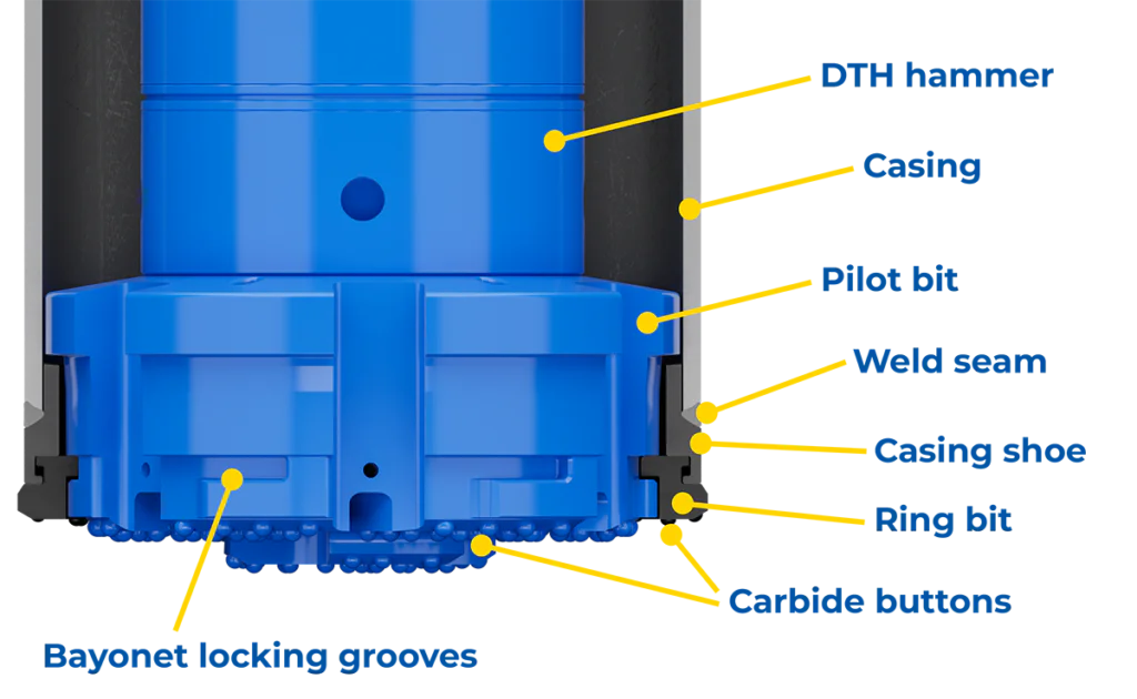
The drill rig’s rotation unit directly rotates the drill pipes, the hammer and the pilot. The pilot bit locks into the ring bit via a bayonet mount by rotating the pilot clockwise as viewed from above. During drilling, rotation speed varies from 5 rpm for the largest pilots of approximately one and a half metres to 55 rpm for small casings with a 114 mm diameter. The pilot bit also rotates the ring bit, but the casing shoe and the casing do not rotate. They only move downward as drilling progresses.
With this method, penetration is not achieved through rotation alone, as this would prematurely wear down the carbide buttons on the pilot and ring bit and result in no meaningful drilling progress. Instead, drilling power comes from the percussion caused by the air-powered DTH hammer, which contains a piston that strikes the back of the drill bit several times per second. This impact frequency varies from 40 Hz for smaller hammers, such as the 4-inch model, and right down to 10 Hz for the largest sizes like 34” or 40”. In turn, the pilot bit transmits this impact energy to both the ring bit and the casing shoe. And since the casing shoe is welded to the casing, the casing itself is also pulled gradually deeper into the ground.
With the forces involved, a single carbide button exerts an extremely high localized pressure over approximately 1 mm2 – enough to easily crush even the hardest rock with a compressive strength of up to 350 MPa, such as dolerite, basalt, or quartzite. As the pilot and ring bit are simultaneously rotated, the carbide button always strikes a new point in the rock a few millimetres from the previous one. This process of impact and rotation chips away the rock evenly and makes for steady progress.
The face surfaces of the pilot and ring bit – the parts pressed against the ground – are fitted with numerous carbide buttons at precisely optimised positions, enough to ensure effective rock crushing without affecting the integrity of the pilot bit and ring-bit. Carbide holes drilled too close together could in the worst case lead to cracking of the pilot or ring bit, and thus failure of the hole in question.
The force with which the drill bit presses against the ground also matters. If feed pressure is too light it will slow down drilling, while excessive force leads to unnecessary wear on the buttons and directional deviation, as the rotation of the bit combined with high friction starts to twist the casing out of a straight line. In the early stages of drilling, the drill rig’s own weight is used to assist with feed pressure, as the purpose of feed force is to counteract the lift created by the compressed air and keep the bit in optimal contact with the rock. As the depth increases, the weight of the drill string also grows as new casings and drill pipes are added to the drill string. At some point, the drill rig must then begin to carry the drill string that is becoming longer and heavier.
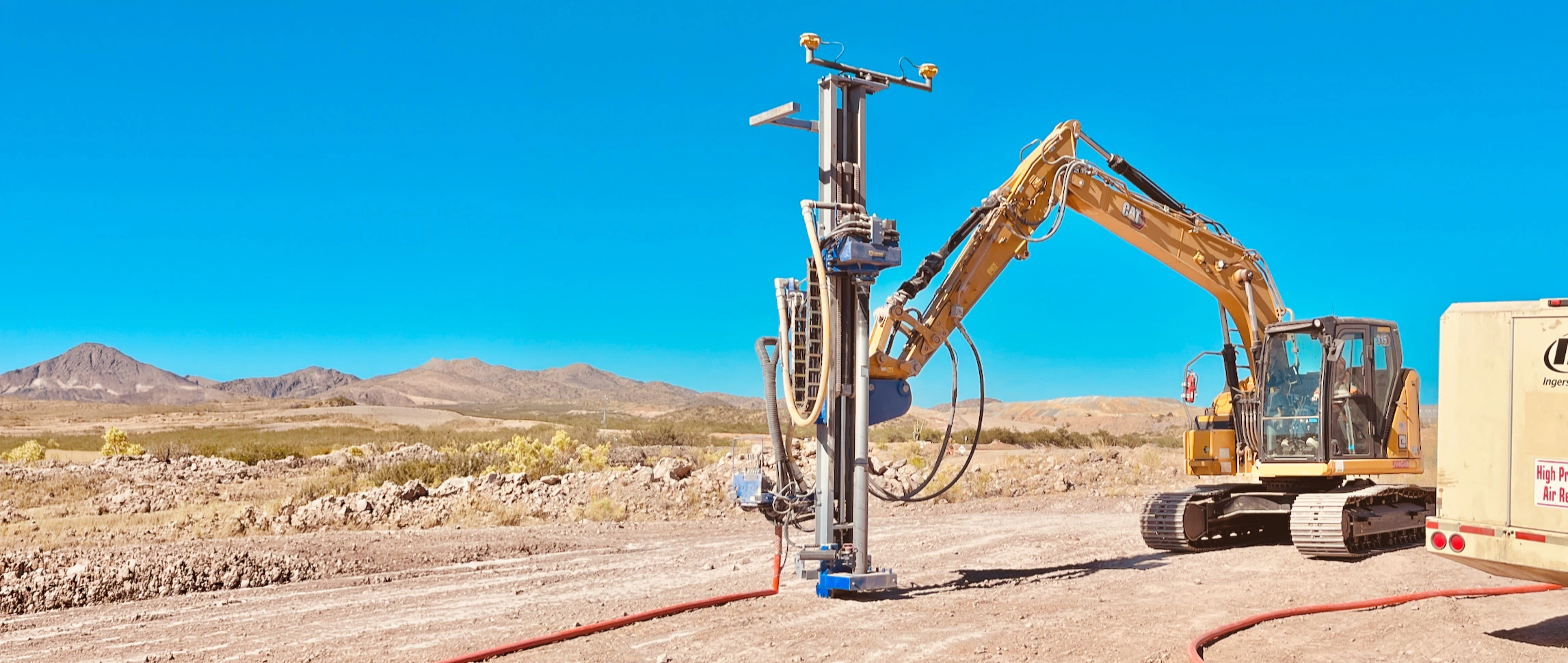
The final element in drilling is the energy source for the entire operation – compressed air. This high-pressure air is fed to the hammer via the drill pipes where its energy is used to cycle the hammer’s piston up and down, by letting the air flow through precisely designed and manufactured channels. This air ultimately exits through flushing holes in the face of the pilot bit. Although the air pressure has dropped close to atmospheric pressure, it still has considerable kinetic energy – enough to blow, or flush, the drill cuttings from the bottom of the drill hole. The exhaust air travels through the ports between the pilot and ring bit into the casing, where it brings the cuttings up to the surface through the annular space between the casing and the drill pipes.
These factors – carbide layout, percussion, rotation, feed pressure, and flushing – enable rock drilling, where even a large-diameter casing can penetrate dense bedrock like a hot knife cuts through butter.
Managing the Risks
Compressed air drilling naturally also carries a risk of air escape. If the exhaust air from a DTH hammer operating at 20–40 bar is directed from the pilot’s face at full force straight towards the ground, the air may penetrate much deeper into the ground than intended, resulting in far more material being flushed out than the volume of the casing being drilled.
This overdrilling can cause also ground settlement or structural damage to nearby buildings, for example. For these reasons, compressed air drilling has been restricted in many densely built urban areas.
To make compressed air drilling safe, it is essential to use only drilling equipment where air control has been properly addressed. In other words, the pilot face should not have large downward facing air holes. The air must instead be directed sideways and back up inside the casing as quickly as possible. This minimises the risk of air escape and enables compressed air drilling to be safely used in city centres, under heavily trafficked roads, and even in earth dams holding back vast volumes of water.
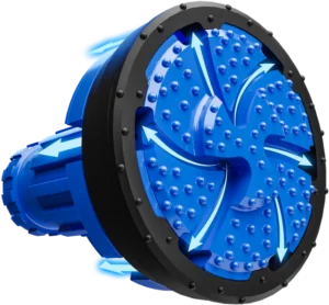
Mincon’s patented Spiral Flush air control technology directs exhaust air away from the ground.
Success Through Careful Planning
In addition to the correct tooling, drilling parameters should also be monitored closely. Even drilling equipment with excellent air control can cause damage if used incorrectly. It is important that the flushing space between the casing and drill pipes is sized relative to the available air volume – ensuring that airflow velocity overcomes gravity.
If the exhaust air cannot lift the drill cuttings up through the casing, it leads to the flushing channel becoming blocked. The compressed air will then seek another path out of the ground, regardless of the air control system on the pilot bit.
Before drilling begins, calculations should factor in ground conditions and location of the drilling site (which will determine the permissible drill rig size and what casing system must be used), as well as the required size and depth of the holes or piles. The optimisation also determines which DTH hammer to use and the required air volume, which will affect the number of compressors required on site.
If you work with an experienced partner that has extensive knowledge of ground drilling methods and products, you can gain a significant on-site advantage. With expert assistance, planning, and calculation, the partner can assist in developing novel approaches for rock-drilling solutions that will save both time and money. Importantly, the partner’s on-site assistance will bring peace of mind – ensuring deadlines are met and budgets are not exceeded.
When you need the help of the industry’s leading expert, get in touch with Mincon’s geotechnical experts, who have hands-on experience from projects around the world.
To learn more about DTH hammer operation, check out the video below. You can also find more information about Mincon’s patented Spiral Flush air control technology and all of our casing systems via the links below. If you’re ready to discuss your next project and success with our team, connect with us at: mincon.com/contact-us
Learn more: Spiral Flush air control technology
Learn more: Mincon’s casing systems